How To Check 3d Printer Firmware? Firmware is a type of software that is programmed into a computer chip. The firmware on a 3D printer tells it how to transform data from the computer into physical objects. In order to make sure your 3D printer has the latest updates, you will need to check its firmware version and update if necessary. Here are some tips for checking and updating your 3D printer’s firmware.
Related:
- Top 7 Best Dual Extruder 3d Printer Under $500
- Top 7 Best Filament For Lithophanes
- 7 Best Hairspray For 3d Printing
- Top 7 Best Direct Drive Extruder
- Top 7 Best Resin For 3d Printer
How to check 3d printer firmware?
After you have successfully purchased a 3D printer, the first thing to do is to establish a connection between your computer and the printer.
In this step, it is essential that you use the correct firmware version of the machine.
In case you have purchased an open-source printer or have received one as a gift from someone else it may be difficult to find out which firmware version the machine uses. But don’t worry, here are some handy tips to help you find out more on how to check 3d printer firmware
Checking your current firmware version:
When checking the printer’s hardware for available updates it includes two options that are alternatives to each other. The first option is to use Repetier-Host which is an open-source 3D printer control software, or you can do this by using Arduino. This option provides all the necessary information regarding your firmware version.
Before anything else, download both applications to your computer and select the one that works best for you. Connect your machine to your computer via USB cable then upload the sketch called “Firmware Updating” to it using Arduino IDE software.
You can check out what are other updates available for your printer on Repetier Host by clicking the Machine menu options. Now click update Firmware and after following a few simple steps, it will tell if there are any updates available for download or not. Once updated successfully it should show up on the right side of your interface as “Firmware version XX.XX”
Checking with the manufacturer:
If you have received an open-source machine, then the firmware checking option is limited to those that are compatible with Arduino. In this case, navigate to the directory called Firmware on your SD card and load up the available sketches which should include a sketch named “Firmware Updating”.
Once done upload it using Arduino IDE software and follow the instructions displayed on the screen.
For some models such as Rambo, you can also check for updates from Repetier Host or Marlin directly.
Click Machine Menu in order to find out more about their information. For other machines, you can download it on the Github page under the marlin and repetier firmware section.
Finding out what other printers use:
If the manufacturer fails to list your printer model, you should try checking with another open-source printer that uses similar hardware as yours or has a compatible design. You can also use Google as a resource that will help to find the needed information by searching for “firmware name + download” such as repetier firmware download.
Generally, this process is similar regardless of the brand but it might be necessary to make contact with the seller in order to get more details on how to check 3d printer firmware version and other useful and relevant information. It may be difficult at first but once you know what type of machine you have, it will become easier to update it.
Now at this point, the only thing left to do is wait for your new firmware upgrade!
Prior to printing, be sure that you are aware of all of its physical dimensions and mechanical features by checking their 3d models on Thingiverse. Not doing so may cause your printer to malfunction which will not only waste more materials but also give you a hard time dealing with fixing problems that could have been avoided in the first place.
If this happens don’t hesitate to reach out at our website or Facebook page in order to get access to helping hands from tech experts who can help fix any technical problems according to your current firmware version. The more information available about open source printers, the greater chance there is of everyone having a great experience.
That is why we strongly recommend checking your firmware version whenever possible and updating it on regular basis to prevent any later malfunctions from happening!
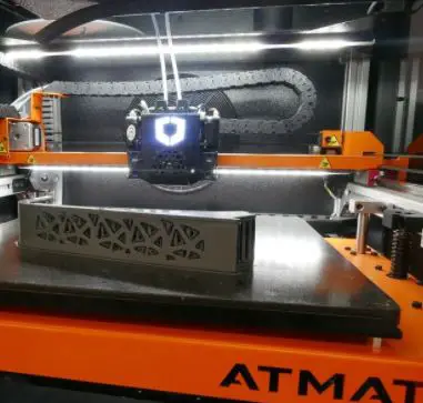
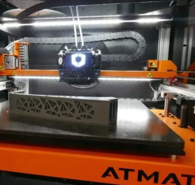
How To Check 3d Printer Firmware? (cre: 3dprinting)
STM32 3D printer firmware
Last week I promised many times to provide more information about the firmware, so here we go.
Working with the STM32 boards is much easier than I expected and I was able to produce a complete G-code compatible printer controller in just a few days that allows me to control all axis and do not rely on any other print controller like RAMPS for example. This means that in theory the firmware can be ported immediately to any 3D printer and it won’t be necessary to spend time re-developing heating control software. It will simply work out of the box if you use an ARM board…
The configuration window is implemented fully in G-code commands, but not in a way that is intended for usage in a printer. It was developed with the primary intention to work with multiple machines and I only implemented the basic functionality needed to control my machines anyway, but it’s very easy to add new features or change existing ones by editing some values at the beginning of each function.
The major differences from Repetier firmware are:
– The motion planner was completely rewritten from scratch and uses precalculated acceleration ramps for all axis [X, Y, Z] [A, B, C] based on cubic functions which allows me to achieve much higher feed rates than 300mm/s without any loss of positioning accuracy!
The positioning speed can be even increased more if necessary since there is no need anymore to move around axes for calculations.
The printing speed can be adjusted in real-time by simply changing the feed rate!
There is no need to change g-code files or click buttons in repetier host anymore, just type in the new value and restart print when ready! This makes it possible to control all axis with much higher accuracy than before because there is no latency between actual print speed and displayed value in host software anymore.
My 3D printer has two Z motors so I could even do color mixing at maximum XY feed rates if I want to! (Currently, I use 16x micro stepping when running only one extruder) – Precise printhead extrusion length compensation based on current feed rate to compensate for filament stretching when retracting [GitHub] – Many little improvements
The printed board design is not final, it’s just the version that I used for testing and already sent to many beta testers. The final version will be much smaller if everything works fine, but currently, it has to be this size since there are no suitable SMD microcontrollers available right now with more than 64kb flash memory… The FET drivers were also removed from the board because they are not needed at all in the current configuration.
– Only one PWM capable MOSFET driver is required [S8050], 3 can be optionally added for printhead heating using external power supply
– High-performance step stick based on Allegro A4954 microstepping driver chip with integrated power MOSFETS [datasheet]
– Only 4 wires required for communication with printer controller, 3.3V and GND power supply – 2 SPI channels available if needed to connect more than one microcontroller/stepper motor driver(s) directly to main controller – 16Mhz bootloader preconfigured with 115200 baud rate that can be activated by sending “$$$” command via serial interface, no need for an external programmer! – 5V tolerant TTL level serial port communication line “Serial Handshake pin” so it’s not necessary to use any additional level shifters or a USB<>TTL converter – MicroSD card slot [GitHub] allowing unlimited printing length without PC connection!
There is also no need anymore to store g-code files on the main microcontroller which saves more than 10% of available flash memory, because you can always transfer the g-code again to the main controller through this slot if necessary.
– Controlled by RepRapPro Marlin firmware with many useful features including G-codes visual display/debugging, M502 command to store EEPROM settings without PC connection or USB<>Serial converters! – Displaying live print progress information on 128×64 graphics LCD screen of Olimexino board (optional accessory)
So here is my current 3D printers control concept in a nutshell…
The “RepRap” printer controller consists of two parts which are connected with a single ribbon bus cable.

Here is how it works in short…
– First board with core controller microcontroller _____ is connected directly to the computer USB port via USB cable ____ – At the same time this board communicates with printer motors/heaters through I2C bus over ribbon cable ____ (through level shifters if needed) – Second board with auxiliary “interface” microcontroller ______ is powered by the main controller and has its own power supply. This second board can be removed or inserted into the interface slot while the 3D printer works without any interruption!
It also provides a user interface on 128×64 graphic LCD screen which allows me to monitor current print progress, make EEPROM settings like max feed rate for all axes at once, control printer functions remotely, etc. – Both boards are connected together using a very fast SPI bus to ease the communication between the main controller and auxiliary microcontroller.
There is no need to waste any I2C pins since there are only two different I2C addresses available.
– For example, the main controller can decide that it’s time to move XY axes without any assistance from the interface board after printing 5 layers… – It sends the Z lift command (motor step number 65535) via SPI bus to the interface board which in turn send this value indirectly (via the main controller) to motors, then waits until it receives an acknowledgment that Z-axis reached requested position through same SPI connection. – At this moment the main controller knows that everything works fine so it can issue the next movement command like X lift (motor step number 65535).
The process repeats itself in a loop.
– Interface board can also control XY axes speeds locally without any assistance from the main controller using 4 PWM capable MOSFET drivers. This allows me for example to set the maximum allowed printhead speed when printing core parts which are printed very slowly, then set much higher speeds on outer perimeters or infill layers where this is not necessary at all…
– SP1 and SP2 pins on the interface board are connected with X min endstop input so there is no need to use any additional external level shifter for this purpose. The only thing you have to do is just connect one wire between the 4th pin on endstop connector(s) and the appropriate pin(s) on the SPI bus (SP1 or SP2).
– Using this concept I now have full control over the printer so it’s possible to do some really cool stuff now! Like for example custom g-codes visual display on 128×64 LCD screen, automatic bed leveling procedure which can use any type of available endstops including inductive (reed) sensors, remote EEPROM settings without a PC connection, a firmware update via USB port, etc.
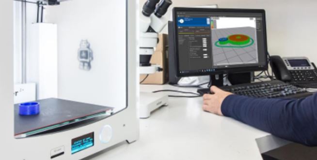
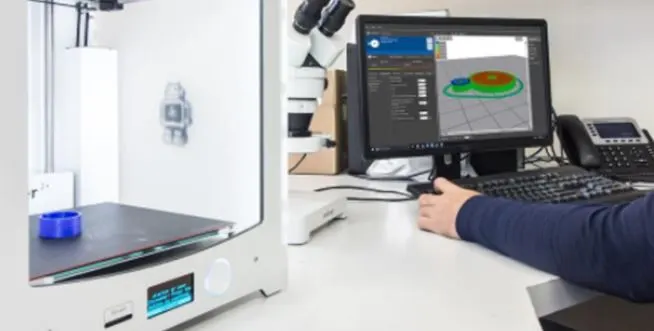
How To Check 3d Printer Firmware? (cre: matterhackers)
Flashing Marlin firmware on Afinibot A31.
There are two ways to flash Marlin on your Afinibot A31 printer: via the LCD menu or writing it directly with an Arduino board.
The best option is to use an Arduino board because it’s more reliable and easier. Here I’ll show you how to do it using a Teensy 3.2 but you can use any other compatible board like RAMPS, RUMBA or RADDS.
First of all download this amazing Arduino program that will allow us to write in binary into our board memory (just select your OS version). Once installed you need to install this plugin for marlin flashing. Unzip the downloaded file and move all the content in C:\Users\{USERNAME}\AppData\Roaming\Arduino15\packages. Finally start the Arduino program and open the Marlin.ino file (File->Open).
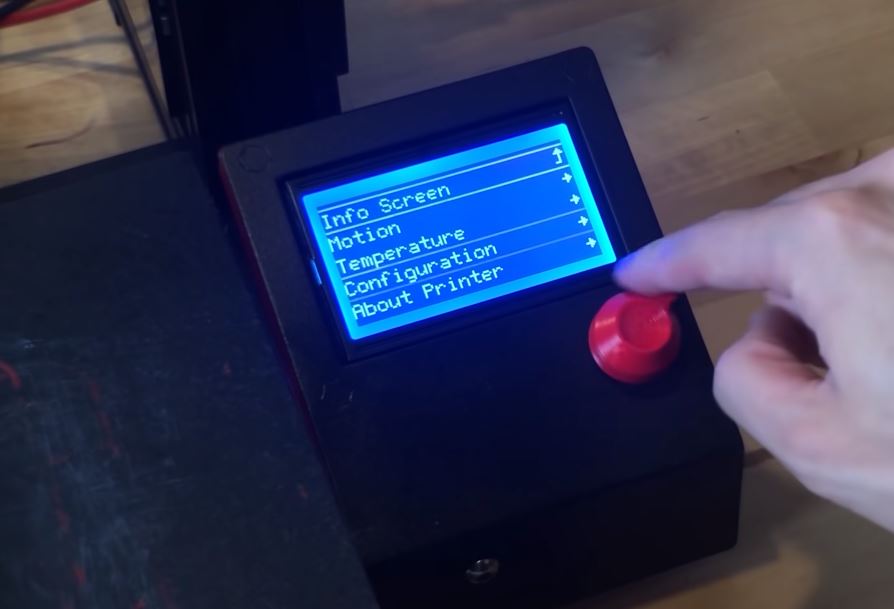
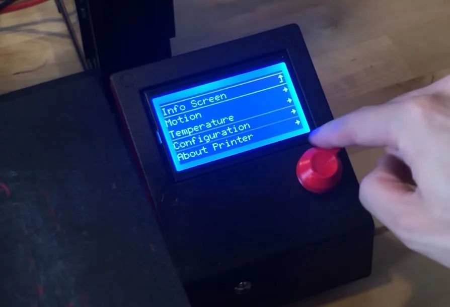
We are ready to flash our first version of Marlin so connect the Afinibot A31 via USB cable and upload the marlin.ino sketch to your board (just keep on clicking Upload) Then disconnect the power supply from the printer, wait about 5 seconds and reconnect it. Your printer’s LCD should look like this:
The first thing you can do with your Afinibot is calibrate its X Y Z axis.
To do that move each axis at one end then press the forward or backward button depending on which direction you want to move (Calibrate->X). Do the same for the Y and Z-axis. The next step is to configure your heat bed but you need some parts to work on Afinibot. I’ve ordered a heated bed from China and I’ll show you how it works soon. In the meantime, you can do a simple test with hairspray or blue tape.
In order to configure your heat bed press Calibrate->Heat Bed, then follow steps on the LCD screen. Finally, install the heater cartridge correctly in place using the M3x14 screw.
When done set the temperature at 20 degrees Celsius and try heating up your hot end but DO NOT TOUCH THE NOZZLE WITH YOUR FINGERS !!!
You should be okay if you wait until it’s hot enough then turn off the power supply and disconnect the AC cord from the outlet. If everything is fine you should feel some air coming out of the nozzle when the heater cartridge is turned on.
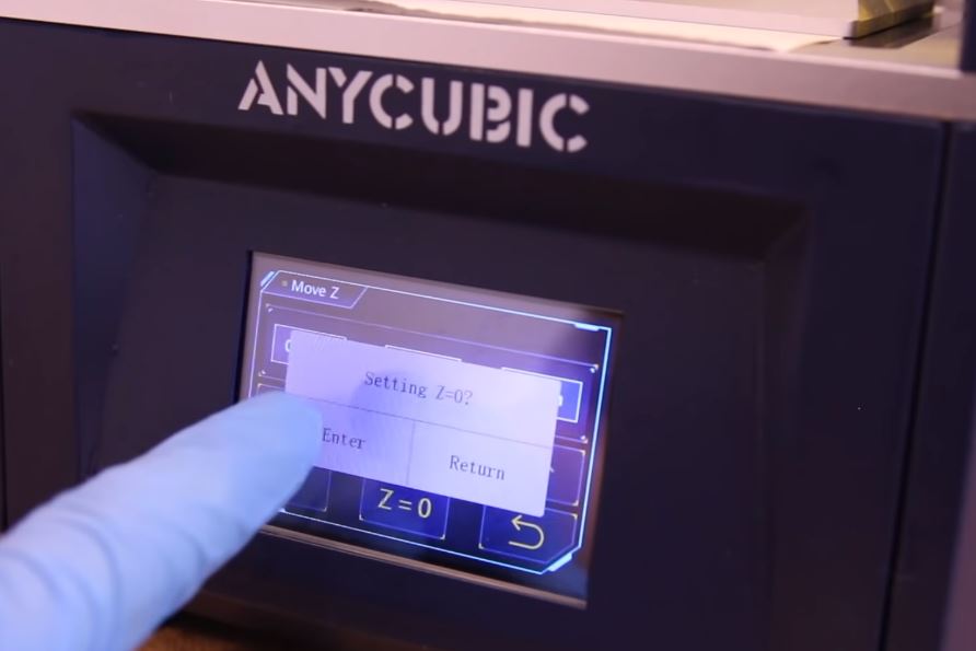
The last step is calibrating nozzle height, to do that go to Calibrate->Height. When LCD will ask you to move the y-axis slowly down this step is done. Check your y-axis position, it should be at the middle of x carriage block top rail. Now move the z-axis up until the nozzle tip touches the bed or until you reach approx 20mm distance between the nozzle tip and heat bed (just try different positions).
If everything went fine LCD menu will say Z=0 now it’s time for first tuning using the G1 command sent by the USB-connected Arduino board via Marlin firmware.
Type G1 Z5 into your Arduino terminal then press the SET button on your Afinibot A31 panel, wait 2 seconds then check your z-axis position.
If it’s not 5mm away from the nozzle tip disconnect the USB cable and check your Z-axis end-stop switch that may be damaged or misaligned (I’ve had this problem).

TH3D firmware, a 3D printer firmware, a library for Arduino-based electronics.
We’re working on it!
But… It is not usable yet!
We currently intend to release it completely OpenSource under GPL3. We will try to use the best practices and make it as easy as possible to help everyone use an Arduino board like Mega or Due (connected by USB) with such a motherboard (with RAMPS-like connectors).
This includes the choice of good defaults which we think should be enough for most users who don’t need/want to change anything before printing.
To reach that goal, we don’t plan to rely on too many “optional” features (driver boards, plugin systems). Nevertheless, we will try hard not to be too strict, if you need to disable a certain feature for compatibility reasons or similar, please contact us!
Conclusion
We hope this article helped you understand how to check 3d printer firmware. If it did, please share the blog post with your friends and family on social media so they can learn about checking their own 3D printers’ firmware too!
Further Reading:
- Top 7 Best 3d Printer For Board Games
- Top 7 Best Creality 3d Printers
- 7 Best Filaments For Ender 3
- Top 7 Best 3d Printer For Nylon
- Top 7 Best 3D Printer For Cosplay Armor
Tags: #Petg #Tpu #Abs #Supports #Panels #Pause #Kidney #Lower #Speed #Creep #Quality #Adhesion #Monoprice #Filament #Firmware #Bed