How to test a 3d printer thermistor with the meter is not difficult. If you have a digital multimeter at home, then it is also easy. You can check whether your temperature sensor or not with each component voltage.
When a temperature of 100 degrees Celsius, the resistance value of the components is about 10000 ohms +/- 1000 ohms.
Each component has its own resistance value that changes with the temperature changes.
Related:
- Top 7 Best Dual Extruder 3d Printer Under $500
- Top 7 Best Filament For Lithophanes
- 7 Best Hairspray For 3d Printing
- Top 7 Best Direct Drive Extruder
- Top 7 Best Resin For 3d Printer
3d printer thermistor resistance chart
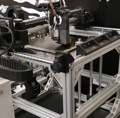
When you have a multimeter at home, you can see on its LCD screen the voltage of each component when testing them on the components of your 3d printer. The figure below shows an example of how to test a 3d printer thermistor using a multimeter:
3d printer thermistor resistance measurement with a multimeter
But if you do not have access to such a tool, then we will show you today how to check whether there is no short circuit in your 3D Printer thermistors or not by using a multimeter.
You can use this method in any case when testing the temperature sensor of your 3d printer with a multimeter.
A short circuit means that resistance is equal to zero, and we will check it in detail in our test

3d printer thermistor short circuit detection
We start by understanding one thing: The normal thermistors have a linear characteristic, i.e., their resistance increases almost linearly with increased temperature. This is due to the fact that the material used for its manufacture has such a characteristic (eg NTC resistor).
In addition, most of them are made up of metal oxides which consist only of pure metals like nickel or manganese and oxygen atoms.
But if we come across a thermistor that has a non-linear resistance characteristic, then it is almost certainly a counterfeit or fake thermistor, which can be used in place of the original components.
If you want to know how this test should be done, here’s a detailed explanation: 3d printer thermistor short circuit detection method
Now we come to the point where we check whether there is a short circuit in the components of our 3D Printer or not.
For this purpose, let’s turn on your multimeter and check the resistance value from both ends of each component with it. In other words, take one end of each solder point that goes into your thermocouple and touch the other end with the other probe that comes out of the multimeter.
Now we will see on the LCD of our multimeter whether it reads a few ohms or more than that. In the latter case, you have a short circuit somewhere in your components and they need to be replaced with new ones.

Cre: mvorganizing
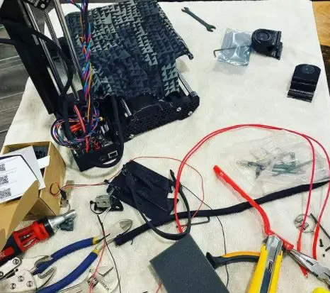
How to test a 3D printer heater cartridge?
The heater cartridge is the part of the 3D printer which actually has to deal with high temperatures. During filament extrusion heating, it sometimes becomes very hot and as such it’s crucial to monitor its temperature. If the temperature is too low, that might be a sign that it needs replacing.
It might also mean that there’s not enough power going to it or something else went wrong (e.g. bad connection) and you’re experiencing voltage drop.
Testing the heater cartridge isn’t difficult and doesn’t take much time – and believe me, if I say even less experienced people should be able to do this by themselves.
All you need is a multimeter (or voltmeter): an instrument used for measuring voltage, resistance, and other electrical properties.
This is how you do it:
Disconnect the heater cartridge.
Connect multimeter probes to A and C (check printer manual for proper terminals). Set multimeter to measure resistance (ohms) or continuity test mode.
Power up your 3D printer
– there’s the voltage on the three pins of the heater cartridge, which means it’s most likely working fine. If you’re using a power supply with adjustable voltage output, set it to maximum (highest setting).
Now check whether voltage goes lower than expected when the heating element gets hot – that is a very important step! Do not continue if that happens. When the heater starts getting hot move one of the probe wires to another terminal while checking for a change in reading.
As soon as you find out which wire is making the multimeter display change, you’ve found out which one of the three pins is touching the ground or not.
Bingo!
Pins are labeled A, B, and C in printers where the hot end consists of 3 separate parts (commonly known as J-Head type). If your printer has a single tube with a thermistor inserted inside, this might be a little more complicated. There are two ways to do it: use a multimeter in resistance test mode or download and print this “heat tester” STL file.
The first option is pretty much self-explanatory, just put one probe at the tip of the cartridge where thermistor wires come out of it (does not apply if the hot end consists of 3 separate parts). If you choose to print the tester, make sure you adjust the scale in your slicer.

Cre: adafruit
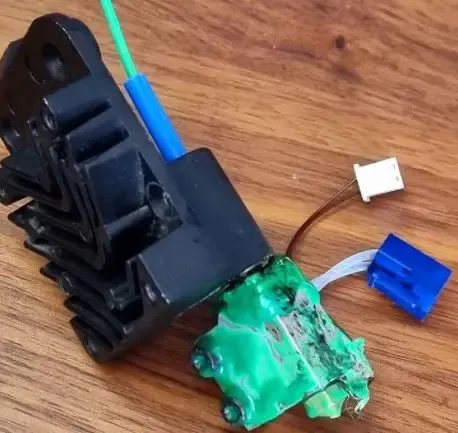
3d printer thermistor
The thermistor is a 3d printer thermistor that reads the real sensing element temperature in ‘C’ or ‘F’ format. It uses a 1-wire communication protocol to send data, so only one wire is required for connecting with your motherboard/controller board! Furthermore, it has an I2C interface intact for future expansion.
Conclusion
The thermistor has a 1/16 DIN form factor and considering the fact that it is designed for high volume applications, we have kept the cost very reasonable. We expect this to be an ideal choice for those who see great value in using a 3D printer controller board that supports reading real temperature other than just the hot end’s heater cartridge
Further Reading:
- Top 7 Best 3d Printer For Board Games
- Top 7 Best Creality 3d Printers
- 7 Best Filaments For Ender 3
- Top 7 Best 3d Printer For Nylon
- Top 7 Best 3D Printer For Cosplay Armor
Tags: #Knife #Supplies #Resin #Bust #Pattern #FEP #Layer #Bed #Warping #Thermistor #Printer #Firearm #Bong