What is the furthest distance a 3d printer can bridge? Various materials have different properties, but polycarbonate is an excellent material for bridging large distances. In addition, with advancements in technology and innovation, this will only become more diverse.
Due to the versatility of these materials, many people are using them to create amazing designs that are impossible to make any other way.
If you’re looking for a new project or hobby to try out, 3d printing may be perfect for you! All it takes is some creativity and imagination!
Related:
- Top 7 Best Dual Extruder 3d Printer Under $500
- Top 7 Best Filament For Lithophanes
- 7 Best Hairspray For 3d Printing
- Top 7 Best Direct Drive Extruder
- Top 7 Best Resin For 3d Printer
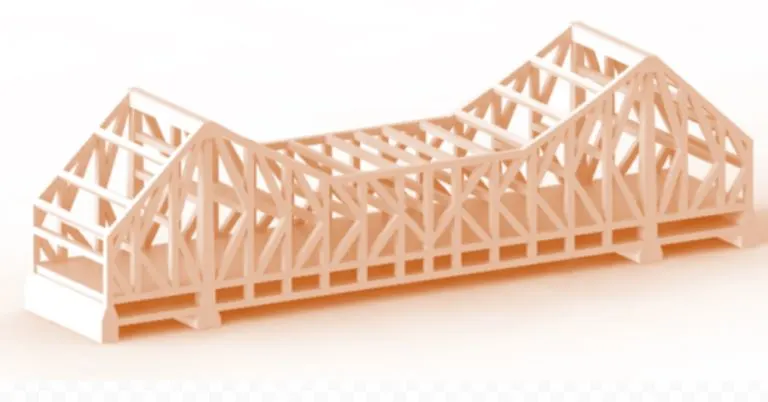
How far can 3d printer bridge?
In one print, you can see what bridges are hard for your printer. Bridges that are 50mm-100mm are good, while bridges that are 150mm or more are excellent.
Philip Rowse of FotisPrinting tested his printer with 3d bridge test file.
He is almost done when I took the photo.
I believe that it will finish soon.
Let’s see. “C’mon Philip!”
And, the result!
He did quite a good job! He can print bridges that are 65-150mm in width. That is a very good bridge printing ability for 3d printer with 0.4 nozzle diameter!
On his blog, Philip is talking about what you should never do in the bridge test file. You may find it interesting, so please check it out.
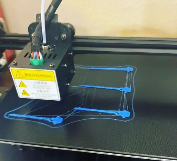
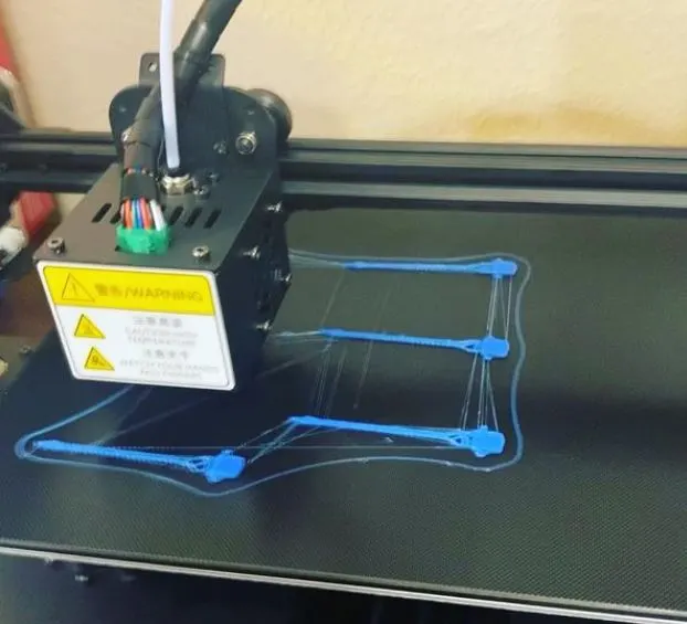
Here is another example of bridge printing by red design.
You can see that for 100mm width, his printer fails in the middle.
It seems that the 200mm width is too wide for his printer!
This time, Lulzbot TAZ4 made a nice print.
If you check this blog, you might find more detailed information about the bridging performance of Lulzbot TAZ4.
This is another example by Philip Rowse.
It failed in the middle for a 100mm width print.
You see that there are diagonal lines on the bottom surface. That means failure location in 3d printer’s nozzle’s path.
If you look closely, you will find that there are diagonal lines on the second layer of the bottom surface. That means that it fails at the very beginning of printing.
Here is another example by Philip Rowse.
It failed in a 40mm width print, but it made a successful print for an 80mm width! It seems to be a fine printer!
Philip also tested his printer for a Z-axis crossing test file. You can read it on his blog
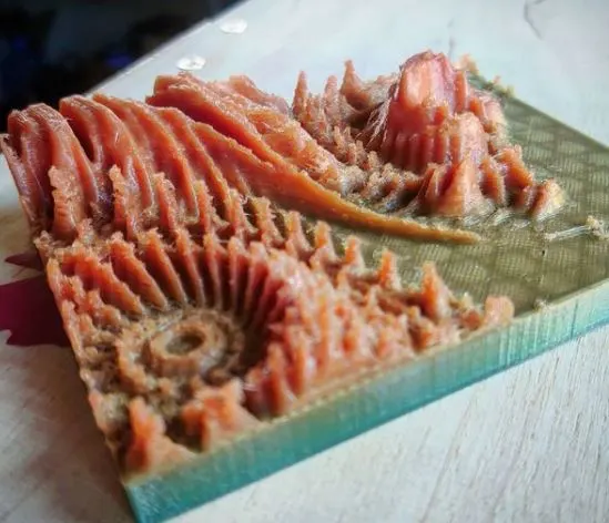
This is another example from 3dprinting3dp. It failed just after 10mm !? I have never seen such a small failure! In my mind, this is the limit of 3d printer. So, if you print a bridge with 100mm width, it has no chance to fail.
Here is an example from Reddit. It made a nice bridge for 50mm width.
For a 100mm bridge, it failed in the middle. This seems that the filament tube is not connected well. Or there were some bubbles inside of the filament? These might cause failure.
I think that the most important thing in the bridge test file is to remove air bubbles inside of filament!
For 100mm width bridges, it failed just after 40mm. It failed suddenly, so probably it’s because of an alignment issue with filament?
This is another example of 3d printing by red design. His printer worked well for 100mm and 150mm width bridges.
I think his printer is good and he can make big bridges!

How Far Can 3d Printer Bridge? (cre: all3dp)
3D Print bridge settings
can be daunting at first, but by following a few simple steps the process makes print the perfect bridge for your 3D printer. If you follow these basic guidelines when configuring your slicer, you’ll save yourself time and frustration when printing your next bridge-worthy object.
This tutorial will teach you how to configure Cura settings specifically for 3D Printing a bridge. If you do not have Cura installed, you can download it from the Ultimaker.
The slicer settings used in this tutorial are as follows:
- Layer height: 0.1 mm Top & Bottom
- Thickness: 1.8mm
- Fill Density: 10% Print Speed : 20mm/s
- Infill speed: 70mm/s
If you have a different Cura, the general process remains the same. The main variable is layer height. If your printer uses 1.0mm filament (like my Tevo Little Monster), use 0.8mm as your Layer Height.
3D PRINTING A BRIDGE OVERVIEW
I’ve broken this tutorial up into 4 parts:
Pre-slicing the model Adjusting the bridge path Rotating the model Fine-tuning the print
You can follow along with my Cura project files below. They have everything you need to get started, including a list of 3D printer settings and the STL file for printing the’ Loop the Loop’ Bridge.
The project files will download to your computer, and you can open them with Cura. Here is a step-by-step tutorial that shows how I print the bridge using my printer settings outlined above:
PRE-SLICING THE MODEL – SETTING UP THE PATH
Start by importing or opening a 3D model in Cura. You should see something that looks like this:
Configure your model orientation using the Rotate tool. This is done by clicking on the rotate icon at the top of Cura and then dragging your mouse to rotate it. I find that it’s best to orient my models so that they are standing upright in the X-Y plane, which is parallel to the floor.
This orientation will ensure that the bridge layers are printed consistently throughout.
Next, scale your model so that it matches up with your 3D printer build plate dimensions.
Using the Move tool, drag and drop the model along the X-Y plane until it lines up with your printing bed.
You can also move individual axes using the Rotate, Scale, and Move tools (probably the most efficient method). After you’ve done this for all three axes, you should be able to move your print around on the build plate freely without intersecting any features.
Now that your model is oriented and sized correctly, move to the Print Setup section in Cura. Click on ‘Print Settings’
Scroll down to sections labeled ‘Perimeters & Supports’. You’ll see a row of settings for the first perimeter layer height. To start, I usually keep these at default values so Cura can calculate the height of the first perimeter layer. This setting will be different for every printer and slicer but is usually between 0.20 – 0.30 mm (0.01 – 0.02 inches).
My printer prints at a resolution of 0.1mm, so I set this value to 0.2mm as well.
Next, you’ll want to configure your infill settings. In the Fill section, set a density of 70% and a speed of 100 mm/s.
Finally, in the Advanced Settings section, I change my print speed from the default 20mm/s to 300mm/s for all exterior perimeters. This is done by changing both Print Speed and Infill Speed.
After this is done, scroll down and click on ‘Generate G-Code’ in the bottom right corner of Cura. A new window will appear with several configuration options:
Click on ‘Use Current’ to save your current printer settings as default (very useful when switching filaments or adjusting settings). Click ‘Export G-Code’ to save the file to your computer. MAKE SURE YOU CHANGE THE FILE TYPE TO STL before saving!
You should now have a .gcode file ready for printing. You can open it with Cura or any other slicer by clicking ‘Open’ in the bottom right corner of the window. If you have a different slicer, the process is similar. Just configure your printer settings as per usual and then load the .gcode file into the software.

How Far Can 3d Printer Bridge? (cre: reddit)
Prusaslicer detect bridging perimeters
Prusaslicer detects whether you are inside or outside of a bridge perimeter. This is useful for crossing bridges without destroying them, which happens if you just cross them without being inside them.
Prusaslicer is capable of both checking whether you are outside or inside the bridge perimeter, as well as returning the bridge name, which can be useful for smart moving. One example is that you can define two waypoints next to every exit of the bridge, and prusaslicer will order an aircraft to fly to the first waypoint, crossing the bridge, and then it will order it to fly to the second waypoint.
You can also define a radius for every edge of bridges.
First, you select one or more edges using SHIFT+click, which will mark them as red circles in your map.
Then once you have done that press CTRL+ALT+B to mark all of the bridges on which you are standing or flying. Prusaslicer will then calculate all of the possible bridge perimeters, and you will get information about them like distance to the edge (distance between your current position and marked point), the exact direction in which you should travel, etc.
Bridging extrusion multipliers with an Arduino
As many of you know, 3d printers can often be very costly to create a solid 3d printer.
One of the most important parts, the extruder has many different types and it’s often something that takes a lot of tinkering to get it working correctly.
Many choose to build their own from scratch, while others prefer to use a kit at a fraction of the cost.
In order for your kit to work, you will have to have a way of controlling the motor that drives the filament into your printer.
This tutorial aims at helping people understand how to use an Arduino with their kit and build a customizable extruder that can be shared among 3d printers!
Background:
This project is based on using a geared stepper motor to drive the filament into your printer.
A typically geared stepper has 200 steps per revolution therefore can step 200mm for every full revolution of the motor shaft. This is also known as a 1/16th micro-stepping motor which will allow for 16 micro steps for each rotation, resulting in 4096 possible positions to place the gear at!
This is why it’s very important to make sure your stepper motor driver is able to do 1/16th micro stepping as well as a minimum of 96ozin (6kg) for holding torque.
Required parts:
Here are the basic components that will be required in order to have a fully functional geared extruder. I have also included links to compatible parts for those who have a preference on where to get their parts from.
1x geared stepper motor. I used a 300ozin (2.3kg) bipolar stepper that had a gear ratio of 1:32. A direct drive extruder is also very simple and can be done by using a single motor, but results in much lower torque and a little bit more slippage with all the gears. You will also need a standard NEMA 17 stepper motor as well as a way to mount it to your x carriage. I find that using a san 112mm stepper is the perfect size even for those who have built a delta style printer, a NEMA 23 stepper will be too large and it’s really not necessary for this project.
1x geared extruder. I used the mk7 direct drive from trinitylabs which can be found here (mk7), however, there are also many other options on Thingiverse such as the delta point delta style extruder. The great thing about using a direct drive extruder is that it will allow you to use the same filament drive on whatever 3d printer you choose.
1x standard NEMA 17 stepper motor. This is used to drive the filament into your printer.
1x micro-switch end stop. This will allow you to easily home your z-axis and normally closes when triggered. You can find a direct mountable version here or any other endstop that uses a lever-type switch (normally closed) will work as well.
2x bearings. These are used to support the filament idler arm. I found these ones on amazon.
1x hobbed bolt. I used one that had a groove that was 8mm wide and 21 teeth, but any hobbed bolt will do the trick!
4x M3 screws between 10-30mm long. These are used to hold your extruder together. This is where you get to decide if you want to use printed parts or not.
1x 1-2mm thick sheet of metal, I used armor plate that I found at my local hardware store. You will need to get it roughly 6″ wide 3″ tall and 0.4″-0.5″ thick. This is where you get to decide if you want to use printed parts or not.
2x bearings that are the same outer dimension as your metal sheet, but you will need to use 2 different sized bearings depending on which type of gears you choose. These are used to make the idler arm and provide great torque for driving filament. I found these ones on amazon (idler bearing), (gear bearing), but you can also search for bearings at your local hardware store.
How Far Can 3d Printer Bridge? (cre: simplify3d)
3D printing holes without supports
3D printers have been with us for a while now. They’ve also just gotten better and cheaper. One of the issues that have plagued users of various 3D printers is how to print holes without supports. Here are some strategies for doing this using software tools.
There are several different ways to approach getting rid of support material from 3D prints. On the low end of the budget scale, you can use a knife to carefully remove support material. That method works but it is not very precise and leaves plenty of room for error. If you’d like to go that route there are some tips here on Instructables.
Another approach is to use software tools to selectively remove support material. A popular free tool for doing this is Meshmixer which works with Windows, OSX, and Linux operating systems. It has several nice features including the ability to cut off support material or “rip” it out of your model leaving a clean hole. Some additional tips are here on Instructables.
Meshmixer also has a feature to hollow out an object using Boolean operations. That is, you can subtract one object from another and it will remove all of the material inside the bounding box of both objects and close up any remaining holes. If you’re curious about how this works there’s a nice example here on Shapeways.
One drawback to Meshmixer
One drawback to Meshmixer is that it doesn’t have a sculpting tool which would be helpful when trying to add or smooth out the exterior of a hollow object.
For this, you can use Blender which has a sculpting feature called grease pencil. The grease pencil allows you to do some simple editing on any mesh surface in your scene and then save out just the edited portion to a greyscale image. You can then use Meshmixer to add the image back into the scene and it will only affect objects in that area of your 3D model.
This is a very powerful feature for adding logos, illustrations or even smoothing out things like bumps on dice.
You can see an example here of a sculpted hole on Shapeways. This image shows the original STL file (left) and the greyscale image (right) that was edited in Blender. Even though this is not really thought of as 3D modeling it is still helpful to be able to make design changes like this without having to reprint your entire object.
Other software tools
There are other software tools available to create 3D models like Meshlab which is very useful for creating or editing STL files. I’ve even made a couple of Instructables about using Meshlab to edit and modify STL files.
As you become more familiar with 3D printing, you will discover new ways to use these types of software tools. Have fun experimenting and let us know if you discover any new tricks or techniques!
The 3D printing experts at Shapeways would like to thank Hot Pop Factory for sharing this post with us. If you’re enjoying this, check out more posts from Hot Pop Factory. And make sure to tell them you came from Shapeways!

How Far Can 3d Printer Bridge?
Can you 3d print overhangs?
Yes, you can! Here are 6 tested techniques for getting the best results when printing overhanging features.
Why would you want to print overhangs? The answer is simple.
If an object doesn’t have enough surfaces in contact with air, it will not be able to stay in place by itself and will simply collapse. This principle alone is why no 3d printer in existence is capable of producing a completely enclosed object without support material being used.
However, there are some designs that offer different degrees of overhangs when printed when compared to their intended design.
These specially designed parts are often called “overhang” parts or are referred to as being “self-supported.”
The degree of overhang you can achieve when printing an object is greatly dependant on your 3d printer’s capabilities.
The more the overhang, the more difficult it becomes to print.
It can become very challenging in some cases when trying to print very large overhangs – almost impossible with current technology.
There are two main factors that contribute to successful overhangs:
#1 Material properties
When it comes to material properties, there are several things that have a direct effect on how well an object prints relative to its ability to support itself.
For example, PLA tends to be easier to print objects using less support material than ABS for this reason – but ABS is stronger and much less prone to bend and can be printed more precisely which is why most serious FDM 3d printers use ABS as their main printing material.
#2 How you orientate the object for printing
Most objects designed with overhangs are meant to be printed standing upright on your build plate.
But placing them like this won’t work well because of gravity.
The answer: rotate the part and print it upside down (and/or at angles). This forces the solvable supports that need to be added onto these parts to end up oriented in a way where they will hold the weight of the object and only needs minimal cleanup after printing with either a knife, file, or sandpaper.
There are many different ways to temporarily support an overhanging part while printing. One method is to use tacks or glue to temporarily hold the object in place until it’s finished printing. Another option is to print the part standing upright (or at an angle) on its side and then rotate it after printing, this requires that you allow your printer software to rotate the g-code for you before sending it to the printer.
This can be problematic however since some slicer software does not support automatic rotation of objects like this unless you manually input specific G92 commands into the code yourself.

How Far Can 3d Printer Bridge?
#1 Method 1: Sticky Tack
The quickest solution for a small overhang is a simple glob of sticky tack. The upside? It’s quick and takes next to no time to implement.
The downside? Your part will have small bits of sticky tack all over it when you’re done printing, along with any other printer artifacts that happen to be on the print surface when the print starts.
It also does not hold up well when dealing with larger surfaces/overhangs so it’s really better suited for smaller prints. For this example, I used a PLA spool holder model designed by Catarina Mota called Spools.
#2 Method 2: Glue Stick
Using an adhesive like Elmer’s glue stick or even spray adhesive is another solution for holding parts in place, but can get messy and potentially damage your build plate if excess glue gets into the wrong places.
Using an adhesive like this also limits the size of your print since you need to be able to get under the part and wipe away excess glue while it’s still wet without damaging the part. If you’re printing in PLA there is a chance that residue from this will melt onto your print if given enough time so it’s best used with ABS or other more heat resistant materials.
#3 Method 3: Hair Tie
One method I’ve seen recommended elsewhere is using a “cheap” hair tie (rubber bands). Just stretch one over your build plate… …and place your prepped overhang parts on top.
This works fairly well for small prints, but due to the low rigidity is not optimal when dealing with larger objects.
#4 Method 4: “Tiny Bear”
Clips I recently came across a different solution for holding down overhanging parts while printing from another maker who goes by Tiny Bear.
There are several other models on Thingiverse, but here’s the one he preferred to use with his Printrbot Simple Metal.

How Far Can 3d Printer Bridge?
#5 Method 5:
Standoff Dolly Another option to consider is a standoff dolly that fits into your build surface and provides a raised platform that supports the bottom of the part while it prints.
I’ve seen two makers who have created solutions for this, one from MakerRax and another from Ooznest.
#6 Method 6:
Buildtak I’m not aware of any printable parts out there yet being designed specifically for this purpose but will mention it here when someone comes across something useful.
One commercial product available now is called Buildtak which you apply to the print surface of your printer, much like a sticker.
After it’s applied you can place objects on top of it and they will stick in place while printing, leaving the bottom clean when finished.
How Far Can 3d Printer Bridge?
3D printing overhang curling fix – the problem
The cause for this is well known and comes from 2 factors. The first one, which you might already know, is that the layers in a 3D printer are not bonded at all.
This means that if we leave a support pillar or an overhang without support it will simply fall down as soon as we remove the supporting material underneath after printing:
Now, this is all well known and most slicing software contains options to fix this problem.
But what can happen during printing is that the material cools down too fast or begins to droop before the printer has finished printing.
This means that good prints can become bad because of such pillars or overhangs which haven’t been printed correctly – like these below:
When you see stuff like this happening, there are 2 things you can do; print slower (to reduce curling) and/or use support structures.
Support structures require post-processing, however, as they usually need to be removed, and doing that wrongly can damage your piece (milling for example).
Although this is a big problem, the fix isn’t too hard to do. Let’s get started!
The solution – using a gap-fill method
One of the easiest ways to solve overhang curling is by gap filling. This means that you print a layer consisting of zigzag lines which gradually increase in height and then fall down again:
This makes gap-fill an easy way to solve these problems for many reasons. The zigzagged areas interlock with each other which prevents them from falling down because they are held in place by the layers below them (the printer doesn’t stop even though it printed nothing!).
Also, turning on retraction can make them turn into tiny support pillars if you don’t need the gaps between them. This means that you get the benefits from both methods; it’s a support, but it can also be easily removed afterward if you don’t need it anymore.
The process – using Slic3r and Cura The easiest way to print gap-filled models is by using either of these software packages: Slic3r or Cura. These are free slicing applications and in my opinion, they’re the best ones in the business (especially when it comes to speed).
I will show you how to set up your models inside both of these programs so that they will come out exactly as shown above.
Slic3r Settings
First up is Slic3r: I highly recommend reading Petr Zahradník’s guide on Cura to understand what the different options in Slic3r mean.
It contains two different models. If you want to modify them, feel free to do so, but make sure that both models are printed at once (both have no infill so they take up very little space). Other than that it should work just fine 🙂
Cura Settings
Since this is simpler than Slic3r, let me quickly explain how to set things up in Cura. First of all, import your model and put it into either the left or right position (I’ll use Right).
Make sure that there’s a gap between the two models (there shouldn’t be any infill or else they’ll fuse together).
You also need to make sure that “Combine Infill” is turned on as shown here:
This way Cura will automatically generate a zigzag pattern so you can save it straight away.
Cura doesn’t have the same amount of options as Slic3r for this, so I recommend sticking to these settings unless your model simply won’t print with this kind of configuration.
The important thing here is that Cura makes sure that both models are combined into one.
You should set the minimum number of layers possible though because too high printing speeds might result in visible seams between them. This means that instead of doing 20mm/s it should be done at 40mm/s (or whatever the maximum is).

How Far Can 3d Printer Bridge?
3D print dome without support sliced with Cura 15.06
printed with PLA (1.75mm) 0,2mm layer height and 0% infill in 15 minutes at 40 mm/sec and 100 °C printing temperature (for the first time it took 25 minutes, but after removing all supports and cleaning the part of old filament it printed in about 15 min.). It was printed on an Original Prusa i3 MK2S.
I used a brim of 10 lines for more stability during printing. The dome is exactly like in the pictures above: 70 mm diameter and 20 mm high.
The oval hole into every hemisphere is 12mm x 8mm – just enough to let some light through but not much so you can look inside. If you want you can add a LED to each eye.
I have printed the eyes with a fill of 10%. It’s quite big but it allows an even flow of filament when printing and also provides enough space for inserting LEDs. The holes in the eyes are 8mm x 6mm (bigger than needed).
If some part is too small I recommend scaling up by 1% or 2%. For some parts bigger than 100% scale go step-by-step always checking if every next step still fits together.
How Far Can 3d Printer Bridge?
3D printing bridges and overhang
3D printing bridges and overhang structures wasn’t a problem, but printing walls proved to be an entirely different story.
In the last few months I have been working closely with Joris Laarman Lab on their experimental metal 3D printer; The MX3D-Metal.
Their goal with this project is to explore how robotic assembly can be used to grow functional machine parts like electric motors and generators, hydraulic pumps, structural beams, and more.
At the end of my internship at MX3D, I had learned not only about robotics and construction printing but also valuable lessons about teamwork and design thinking.
I was honored to be part of this experiment that has potentially game-changing implications for construction, architecture, manufacturing… the possibilities are endless!
The MX3D-Metal printer uses two six-axis industrial robots and welding to additively fabricate functional structures.
During my internship, we focused on the development of a robotic process that could build structures using stainless steel wire instead of laser powder bed fusion (the MX3D’s current method ).
This required us to design, visualize and test new programming methods, building strategies, and hardware setups.
I was part of an amazing team, including software developers, engineers, architects, and designers. They taught me so much during my time at MX3D!
Conclusion
3D printing is a fascinating and rapidly advancing technology. It has the potential to completely change manufacturing as we know it, but how far will this go? What are some possibilities for what can be made with 3D printers in the future? We’ll have to wait and see!
Further Reading:
- Top 7 Best 3d Printer For Board Games
- Top 7 Best Creality 3d Printers
- 7 Best Filaments For Ender 3
- Top 7 Best 3d Printer For Nylon
- Top 7 Best 3D Printer For Cosplay Armor
Tags: #Technician #Nozzle #Supplies #Filament #Bridge #Vented #Plastic #Medical #Classroom #Change #Image #Harmful