Can You 3d Print Bearings? 3D printing is one of the most innovative technologies that has hit the market. It’s rapidly growing in popularity, and it can be used to create just about anything you want, including bearings.
If you have a 3D printer at home or access to one at your workplace, then you can use it to print bearings for yourself or your company.
The process of 3d printing is simple enough that anyone who knows how to operate a computer should be able to do it with relative ease.
You simply need an idea of what kind of bearing you’re looking for (or someone else will design the blueprint) and the appropriate materials available on hand (like copper wire).
Related:
- Top 7 Best Dual Extruder 3d Printer Under $500
- Top 7 Best Filament For Lithophanes
- 7 Best Hairspray For 3d Printing
- Top 7 Best Direct Drive Extruder
- Top 7 Best Resin For 3d Printer
Can you 3d print bearings?
Yes, you can 3D print bearings. My friends and I have a concept for a device that allows skaters to 3d print their own skateboard components very cheaply.
We are wondering if bearings can be 3d printed? They would need to fit the standard 608 sizes, but they don’t have to last very long since they’re just prototypes. If we were able to print bearings, it would be less expensive to prototype and help us save money in the long run.
3D printed bearings are a difficult problem because of the forces involved. For a skateboard wheel, you need low friction bearing surfaces under heavy loads at high speeds so your design requirements get pretty technical really fast! I have been asked this same question before about bearings for STEM projects, another reason to go with steel 608s.
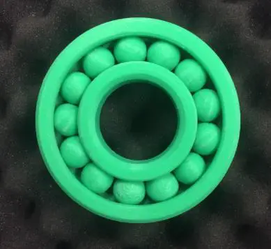
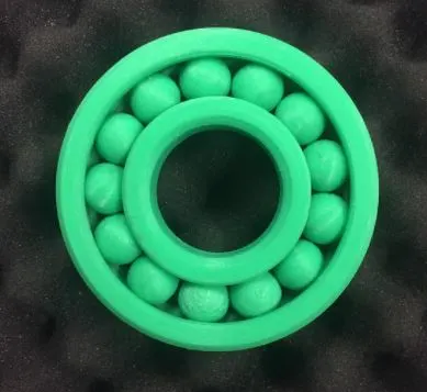
3D printed bearings must fit a standard 608 size. The bearing sizes are shown below:
- Bearing Size Dimension (mm): 608 8mm
- Ball Diameter: 19 1.18 28.4
- Number of Balls: 626
- Inner Diameter: 10mm
The inner diameter is the hole the axle goes through, and it has an interference fit with the outer diameter of your spindle so you need to design something that works with both parts as a system. I would go for a press-fit or some other kind of interference fit so you don’t have to rely on glue or fasteners to assemble your machine part.
The bearing itself must also be very smooth in order to reduce friction. If the surfaces are rough, then you will find it much harder to push your load around.
There are a lot of engineering things that need to come together when designing the “bearing” part of a skateboard wheel, so I am not sure if this is something 3D printed is for. It would take more research on each aspect of the design before I could give you an informed answer. You can get bearings online at stores like eBay or Alibaba.

Can You 3d Print Bearings?
3D printed linear bearings
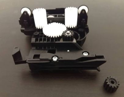
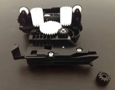
The aim is to create a planetary gearbox at a low cost with available resources.
By now, it’s possible to print linear bearing components with ABS or PLA filament on consumer FDM printers. The printer is capable of extruding plastic in filament form which leads to the possibility of creating any type of geometrical shape including this one. I’ve used my Ultimaker 2 with a 0.25mm nozzle for printing the parts.
This way, quite high precision is achieved while keeping the production costs low due to less material necessary and fast printing speed. For applying pressure onto the bearings I simply made some roller wheels out of 3mm transparent acrylic rod (Plexiglas).
I’m quite happy about how everything turned out; especially because I didn’t need any special tools or machining while creating this planetary gearbox.
I even managed to create a solution for reducing the stepper motor speed by using a small gear with 50 teeth and two pairs of coupled smaller gears as shown in the picture below. This way, the output speed is reduced by a factor of 25 compared to input which is sufficient given my application.
3D printed bearing generator
To start this little series of posts, I’ll describe how to build a simple 3D printed ball bearing generator.
I stumbled upon this idea some time ago, but I’ll describe how to build it step by step using new parts.
The goal is to transform the rotational motion of a rotating shaft into electrical energy thanks to an alternator.
It’s not completely new – for instance, you can find similar applications. The principle isn’t limited only to generators: if you apply a brake pad on the rotor (i.e. stop it), then it turns into a motor that drives the shaft with the same speed as its former rotation; on second thought, if both rotor and stator are passive then this device becomes just a transformer that could be used to transfer energy from one circuit into another one. In any case, it’s an interesting experiment to perform, so let’s begin.
Can You 3d Print Bearings?
STEP 0: MATERIALS & TOOLS
To build the generator you’ll need some cheap materials you can easily buy on eBay or Amazon . You will also need some cheap tools that are found in every home.
The required components: 1x ball bearing (608 sizes) 1x neodymium magnet 7mm x 2.4mm x 1mm (or similar; search online for stronger magnets) ~60cm enameled copper wire (22AWG should be ok) 4 small bolts and nuts (M3 thread is recommended) Oh yeah! We’ve almost got all we need! For tools, besides those that I mentioned above, you’ll need: 1x pair pliers (cheapest possible) 1x screwdriver (preferably flat-head, not Philips) 1x wire stripping tool
STEP 1: CRANKSHAFT
The first thing you’ll need is to design a “crankshaft” that will be used as the rotor of the generator. It’s very easy and can be done using SketchUp. Just draw a few circles and cylinders, and join them together using the Line tool. Be sure to leave an allowance of about 2mm around your magnet so it stays inside its pocket when you’ll mount the stator on top of it. I’ve included other details in my model which are not totally necessary for this step – they shall appear later on when we design the stator.
Keeping it simple We can do better than that! If you search online, you will find lots of cool crankshafts made with SketchUp. I’ve tried to import them into my model using Google’s plugin but didn’t succeed. Or maybe I just did something wrong…
STEP 2 : STATOR (ALTERNATOR)
Now let’s design the other half of our generator: a stator (or alternator). The one I used was designed by Vladimir Jankijevic – thanks, dude! Again, if you search around on Google or Youtube, you’ll find files for this part in Sketchup format (for example here ).
Keep in mind that this is meant to be laser cut from thin wood. If you’re going to use a 3D printer, then 3mm acrylic works fine.
The rotor part has been modeled by Daniel Chieusse.
It’s meant to be cut from the MDF board, but any other material should work as well. Fortunately for me, I had some scraps lying around so I used them instead of buying new stuff! The complete files can be downloaded here: stator and costs
STEP 3: THE WIRES
Now let’s prepare the enameled copper wire we’ll need to build our coils: first, we cut it into about 60cm pieces (we’ll use two per coil); next, we strip off the enamel insulation with our wire stripping tool; finally, we twist its strands into a “rope” which will be used to wind around our coils.
At this point, you’ll probably notice that the bolts and nuts I’m using are too big for our generator… But don’t worry! We’ll get our hands on some M3 screws and nuts before proceeding any further.
Unfortunately at this scale, even a small coil looks huge – but we’re going to simplify it in the next step.
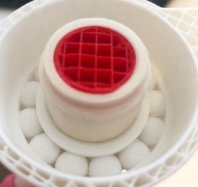
Can You 3d Print Bearings? (cre: thingiverse)
STEP 4: SIMPLIFYING THE WIRES
Now let’s try to make things less complicated by simplifying those wires!
Open your model in Autodesk Inventor, add a new sketch with two horizontal lines at a distance of 10mm from each other, use them as references while adjusting the wire to this distance (trying not to leave any gap), and finally give the resulting shape a circular profile.
STEP 5: SIMPLIFYING THE COILS
As I mentioned before, we’ll wind two coils around our stator: one on the top part and another one on the bottom. The coil on the top is mounted between two metal plates that keep it in place; while the other sits inside a small hole we will drill into the bottom plate of our device. The first thing you want to do is to draw your coils and intersections over a sheet of paper so they can be easily traced and cut out with a pair of scissors:
Now let’s open our model in Autodesk Inventor, make sure your sketch is correct, and extrude it to a distance of 5mm so we can create a profile with a circular outline. Remove the lower line which is not needed anymore.
STEP 6: THE STATOR/ALTERNATOR ASSEMBLY
Now let’s assemble our stator/alternator! First, we need to fix the top plate between two M3 nuts that will be screwed into T-slot connectors on either side of our device:
Next, we have to drill some holes for mounting the coils, followed by tapping them using an M4 screw and nut. It’s worth mentioning that my bottom coil was designed around a 2mm hole – I’m quite sure it would work as well with 1 or even 3mm Holes…
But you will have to test that out yourself. In the end, we just screw our stator into these holes, and then put a few drops of superglue on it so it won’t move around while we’re assembling the rotor – which is up next!
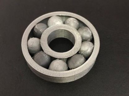
STEP 7: THE ROTOR
Now let’s prepare the rotor part: first of all, I’m going to suggest printing two copies of this file (so you can fix them together with some gorilla glue if needed), but you might get away with just one since there are no critical dimensions.
Just make sure your bottom bearing fits correctly inside its housing if you don’t use two parts.
Also, notice that there’s a slot for mounting bearings on either side, so do keep in mind that you’ll need at least four bearings (two per rotor).
Can You 3d Print Bearings? (cre: instructables)
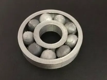
STEP 8: ROTOR ASSEMBLY & ALIGNMENT
Then let’s assemble the rotor: first, we put a piece of MDF inside, and then we drill some holes through its base for mounting it to our motor shaft – adding T-slot nuts on either side.
You might want to use your bolt and stator to figure out how much clearance we need between our coils and bearings, but whatever works best for you… Just keep in mind that there should be enough space so it doesn’t hit any other parts while spinning. Once this is done, we add four bearings and screw the whole thing into place:
And finally, add two more T-slot nuts on either side of our bearing to keep it from moving around, and we’re set!
STEP 9: THE MOTOR
Now let’s take a look at the motor: one thing you’ll immediately notice is that this model uses one half of an old CD spindle to form its rotor – so we should use this same piece for building our electric motor.
You will also need four small metal washers and some screws to attach all these parts together: first drill two holes through your rotor and mount it onto the bottom bearing housing with T-slot nuts; then add another bearing inside (without any T-slot nut) – before screwing the whole thing into place.
Well, that’s pretty much it as far as mechanics go… The only thing left to do is add a small piece of wire that will provide a way for current to flow from one coil towards the other.
STEP 10: WINDING THE COILS
Now let’s move on to winding coils – in order to make our own, we need a thin piece of insulated copper wire which will be used as base material: start with cutting off a 100cm long strand and remove its insulation by melting it away with some help from your lighter or soldering iron.
Once you have the bare core, tightly wrap it around one half of your spindle while adding glue or wax at certain intervals so it won’t shift its position when moving onto the next step.

Can You 3d Print Bearings? (cre: sciencedirect)
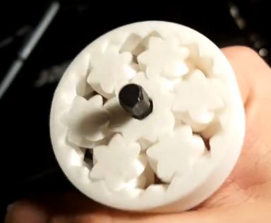
3D print gear bearing
3D print gear-bearing squirrels have been around for a while now, but this is the first time we’ve covered one. This particular example called “Gearsitus Maximus” by Thingiverse user ekulnayar was inspired by Vicente Soler’s gear-bearing bunny and took about 8 hours to print.
Our favorite part – it actually works! We’ve seen other 3D-printed gears that work, even ones on Thingiverse, but none of them have ever moved quite as smoothly as these.
For those curious, the majority of what you see here is actually infill – so little of the actual model touches another gear or pin except at their bases.
There are four gears in here, all with different tooth counts to adjust the speed at which they turn. As a result, they can be combined to provide different overall speeds for Maximus or left on their own.
Conclusion
3D printing is an incredible technology that has the potential to revolutionize many industries. It’s also true, however, that one of the biggest drawbacks with this new manufacturing process is its inability to produce some common mechanical parts like bearings.
This limitation will eventually be overcome as engineers and manufacturers develop more advanced printers capable of producing these small but essential components.
Until then though, you’ll need to find another way to get your hands on them if they’re not already stocked in your inventory or readily available from a supplier.”
Further Reading:
- Top 7 Best 3d Printer For Board Games
- Top 7 Best Creality 3d Printers
- 7 Best Filaments For Ender 3
- Top 7 Best 3d Printer For Nylon
- Top 7 Best 3D Printer For Cosplay Armor
Tags: #Cookie #Dice #Brass #Ceramics #Carbon #Blender #Bones #Receiver #Beyblades #Bearings #Drone